Submitted by:
Glenn Clark
VersaTech Electronics
The programs and drawings shown below are taken from the examples section of the manual.
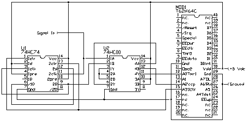
The TICkit has a pulse_in function which works very well for measuring pulses provided you know when they are coming. The TICkit does not need to be doing anything else while it waits for the pulse to occur. This generally is not the case in the real world. This next application demonstrates how the CCP output can be used in conjunction with timer1 and some discrete logic to make a very precise pulse measurement system that measures in background while the TICkit continues its other tasks. The CCP output is configured for PWM output like in previous examples. This time, however, we are not as interested in the duty cycle as the period. Lets say we are interested in pulses that are very fast and we want a resolution of 1 microsecond. The oscillator on a 20MHz TICkit produces a period of 0.2 micro seconds. This means we want to divide this by a factor of 5 to produce a period of 1.0 micro second. This is accomplished by loading the Timer2 period register with a value of 4. The CCP register is loaded with 2 (for a 50% duty cycle) and the output on the CCP pin will be 1 MHz or have a period of 0.1 us. We then gate this signal with an and gate and some trigger logic which feeds the Tmr1 pin (pin_a0). Now reset the trigger circuit and examine the contents of timer1 as soon as it remains constant at any value other than 0, we have measured a pulse. The contents of timer1 is the count of microseconds the pulse was high. The circuit for this follows:

The circuit for gating the time base uses two flip flops (special logic components that hold their state until reset). The TICkit arms the circuit by bringing pin_a3 low and then high. The next rising edge on U1-2clk will turn U1-2 on and allow the time base to get through to the input of timer1. As soon as U1-2 turned on, U1-1 is clocked and turns on as well. Because the D input of U1-2 is connected to /Q of U1-1, the next pulse on the signal will turn U1-2 off permanently before any of the time base can be counted. So, at this point, the count in the TICkit's timer1 represents the amount of time that the signal was high. The program for this circuit follows: