Submitted by:
Glenn Clark
VersaTech Electronics
The programs and drawings shown below are taken from the examples section of the manual.
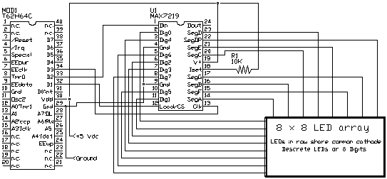
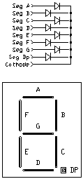
In the last examples, we used the I2C bus to communicate to peripheral ICs. The I2C bus is sometimes called the 2-wire bus. In this example we will use a 3-wire bus, another serial standard, to communicate with a MAXIM IC designed for driving multiplexed numeric LED displays. The IC is the MAX7219 8-Digit LED Display Driver. This IC drives a matrix of LED's so that 256 individual LED's can be driven from a single 24 pin IC. The magic of this technique is called multiplexing (time multiplexing to be exact). This means that at any given point of time, only 8 LED's are being driven, but each 8 LED's is driven in quick succession over time. Our eyes interpret this blur as the desired pattern; all LED's which received any drive appear to be on continuously. This is similar to our first example where two LED's blinked alternately, when there was no delay in the loop, both LED's appeared to be on continuously. This IC is called a digit driver because 7 segment LED digits contain 8 LED's (7 segments and a decimal point) that share a common cathode or anode. By connecting all the same segments together and calling them rows, and using each of the 8 digits common cathodes at columns, an 8 x 8 matrix of diodes is created. If you just want to control LED's and not digits, you can electrically arrange your diodes in groups of 8 that share a common cathode. This has been done often for Christmas displays. The circuit for this example is shown below. There are no real surprises here, multiple 7219s can be daisy chained for more LED drivers yet. The program simply lowers the "load /CS" line, shifts 16 bits of data into the Din pin using the clk pin, and the communication is complete. A resistor is used with the Iset pin to Vdd. This sets the maximum drive for any segment


The program for interfacing to the 7219 is also elementary. Each communication sends 16 bits which is comprised of 8 data bits and 4 bits of register address. The remaining 4 bits are unused. The 16 bits are sequentially shifted out the D2 pin and clocked into the 7219 using the D3 pin. The 16th bit shifts out first and each bit is latched in on the rising edge of clk. A subroutine takes care of shifting out the 16 bits. DEF statements define constants used to refer to each of the registers in the 7219. The program simply lights every LED in each row then every LED in each column in succession.