Submitted by:
Glenn Clark
VersaTech Electronics
The programs and drawings shown below are taken from the examples section of the manual.
A common problem encountered when designing controller applications based on single chip controllers is the lack of I/O or other controller resources. To meet this demand for additional capabilities, a trend has developed toward serially connected peripheral ICs. One example of this is Protean's I2C Xtender IC. This device is a specially programmed IC that responds to commands over its Inter-Integrated Circuit (IIC or I2C) bus. This bus connects to a host processor using only two wires. If a TICkit is the host, the connection can use the EEprom bus wires leaving all 16 of the TICkits general purpose I/O lines available. Up to 8 or more Xtenders can be connected to a single host via these two lines.
A single Xtender IC gives the system the following hardware resources: 2 CCP I/O pins, a 32 bit real-time seconds counter, 3 time bases, a unipolar stepper motor controller, 128 bytes of RAM, a buffered RS232 port, a 16 bit counter, 4 100-Hz PWM outputs, and 5 8-bit A/D channels.
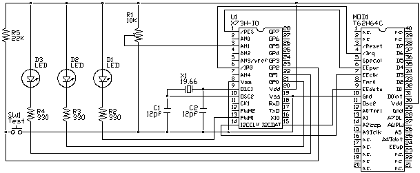
A sample connection to an Xtender is shown below. The I2Cclk and I2Cdata lines form the logical connection. In addition to these lines, the /IRQ line, and /RES of the Xtender are connected to the /IRQ, and EEpwr of TICkit respectively. A sampling of I/O components are connected to the Xtender in the diagram to demonstrate the A/D, PWM1 (CCP1), button input, general purpose output, 100 Hz PWM and time base outputs.

In the program that follows, every press of SW1 causes a read from the RTC seconds count and a read of A/D channel 1. You can vary the input to the A/D channel by changing the position of R1. To make the operation of the A/D clearer, you can use a multi-turn version of resistor R1. LED D3 follows the status of SW1 except that it inverted to demonstrate TICkit processing. LED D2 shows the effects of the 100 Hz PWM. LED D1 shows the effects of the PWM1 output which is a hardware generated, higher frequency pwm. LED D1 and D2 bright and dim out of phase with each other so that while one gets brighter, the other gets dimmer.
There are many more things that the Xtender can do and programming the Xtender is a subject in and of itself, but this example shows how simple register write and reads accomplish control of the Xtender. Communication with the Xtender takes place at the same speed as communication with the EEprom on the TICkit (400 Kbps) so it takes commands very quickly.
Commands for the Xtender are formed from constants contained in the Xtender's library. Use the '|' vertical bar character to combine the device number with the specific command. This method keeps the code very clean and readable.