Switch Input and Debouncing
(Including key matrix techniques)
Submitted by:
The programs and drawings shown below are taken from the examples section
of the manual.
No matter what your project is, a simple user interface is often required.
A user interface usually consists both of a way to tell the controller
what to do, and a way for the controller to tell you what it is doing.
We have looked at LED's as a way for the controller to indicate its status,
but how do we tell the controller what to do, aside from changing its program?
The most common answer to this question is a collection of buttons and
switches. This can vary from a few push buttons to accomplish a "wrist
watch" type of interface, to a full 84 key ASCII keyboard.
We touched on the concepts relating to switch input in the rotary encoder
example. The basic electrical problem is to make an SPST button (single
pole single throw) produce the voltages required by the digital circuits
of the controller. The solution is to use a resistor to either pull up
or pull down the voltage when the switch is open. The next circuit example
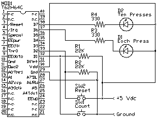
uses two switches and two LED's. As shown in the schematic below, the switch
SW1 is wired so that it connects the pin labeled D1 to ground when it is
closed. When SW1 is open, pin D1 sees +5 volts through resistor R1. R1
is called a pull-up resistor because its function is to pull a digital
line high when no other component is driving it low. Conversely, SW2 is
connected so that when closed, it connects the TICkit pin labeled D2 to
+5. R2 pulls pin D2 low when the switch is open, so it is called a pull-down
resistor. Both SW1 and SW2 are momentary push buttons, which means they
connect only while a being pressed.

The program shown below uses the circuit above to implement a meaningless
program. When SW1 is pressed 10 or more times, LED2 lights. LED1 will light
every time SW1 is pressed. Button SW2 resets LED2 if it is on and restores
the count of button presses to 0.
DEF tic62_c
LIB fbasic.lib

GLOBAL byte press_count 0b

FUNC none main
BEGIN
    REP
        IF pin_in( pin_d1 )
            ; do nothing the button is not pressed
            pin_high( pin_d6 )
        ELSE
            ; button is pressed
            pin_low( pin_d6 )
            IF <( press_count, 10b )
                ++( press_count )
            ELSE
                pin_low( pin_d7 )
            ENDIF
        ENDIF

        IF pin_in( pin_d2 )
            =( press_count, 0b )
            pin_high( pin_d7 )
        ENDIF

        ; try putting the following in the program later
        ; delay( 20 )
    LOOP
ENDFUN
When you type in this program, leave the delay( 20 ) line commented
out, and execute the program. You will find the results unsatisfactory.
The 10 count LED seems to light too soon, sometimes it lights on the first
key press. Why is this?
The reason has to do with the physical nature of a switch. Most switches
bounce their contacts due to the mechanical properties of the switch. This
means that for a few milliseconds, the contacts are closing and opening
for a random number of times. This TICkit processor is fast enough to catch
these very fast bounces which look like repeated key presses. Now put the
delay(20) line in the program by removing the ';'. The delay of 20 milliseconds
makes the program insensitive to key bounce and thus it works just as we
expect. Often, there is no need for an extra delay when debouncing keys
in a program. Many times there is enough delay associated with the main
control function too make the key scanning insensitive to key bounce.
Our next two switch examples involve scanned key matrix. It may seem
like a lot of added complexity to scan a matrix of keys when compared to
the simplicity of running each switch to an I/O line on the processor.
In fact it is more complex, but it uses fewer I/O lines as the number of
keys grows, and it requires fewer steps to determine if any keys are pressed.
This can save processing time because keyboards spend most of their time
with no keys pressed.


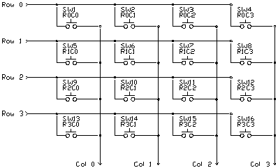
Notice in the first diagram that each key connects a unique combination
or row and column wires. It is the combination of row and column that allow
the microcontroller to determine which key is pressed. The number of rows
or columns may change in different keypads, but the basic idea remains
the same. Your program needs to determine the exact meaning of each key.
Some keys may produce specific actions, other keys may be converted to
ASCII characters for display or for use as data.
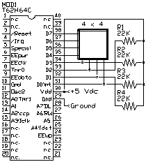
The first circuit uses a 16 key matrix arranged as 4 rows of 4 columns.
We bring one row of the four low to see if any keys are pressed on that
row. The four column inputs are then read to see if there are any lines
low, if so, the corresponding key is pressed. It is important that only
one row output be low at a time to correctly identify a single key press.
The column inputs are all tied high with pull-up resistors to make the
inputs high when no key is pressed. If appropriate, however, the program
could make all row outputs low and read the column inputs. If all the column
inputs are still high, none of the keys are pressed. This can be a useful
way to determine if program time needs to be devoted to keyboard scanning.
The following program demonstrates the technique used to scan a key matrix
directly.
DEF tic62_c
LIB fbasic.lib

GLOBAL byte scan_row 0y11111110b
GLOBAL byte scan_col 0y00000001b
GLOBAL byte scan_number 0b

FUNC none main
BEGIN
    dtris_set( 0y00001111b )
    REP
        dport_set( scan_row )
        delay( 1 )
        IF b_and( dport_get(), scan_col )
            ; no key is down go to next scan
            ++( scan_number )
            IF ==( scan_col, 0y00001000b )
                =( scan_col, 0y00000001b )
                IF ==( scan_row, 0y11110111b )
                    =( scan_row, 0y11111110b )
                ELSE
                    =( scan_row, <<( scan_row ))
                    ++( scan_row )
                ENDIF
            ELSE
                =( scan_col, <<( scan_col ))
            ENDIF
        ELSE
            ; key is pressed
            con_out( scan_number )
            REP
                delay( 10 )
            UNTIL b_and( dport_get(), scan_col )
        ENDIF
    LOOP
ENDFUN
There are only a few tricks to key scanning. The first is to allow time
between when you write the row scan out and when you read the scan result
in. The second is to make sure that all keys are released after a key press
is detected, before you detect the next key press. If you do not do this,
multiple keys depressed accidentally can lead to completely wrong interpretations
about key presses. If you need multiple keys to be pressed simultaneously,
like a shift or "alt" key, put all those keys on a separate row.
You may even wish to put diodes on these keys.
This key scanning circuit also uses a few CMOS logic ICs (integrated
circuit). This is to illustrate the use of such circuits and how they can
save microcontroller I/O. This circuit can scan up to 64 SPST normally
open switches, and uses only 7 I/O lines.
 DEF tic62_c
LIB fbasic.lib
GLOBAL byte key_value
GLOBAL byte ascii_value ob
FUNC byte key_lookup
PARAM byte key_in
BEGIN
=( exit_value, '?' )
IF <( key_in, 10b )
=( exit_value, +( key_in, '0' ))
ELSE
IF <( key_in, 36b )
=( exit_value, +( -( key_in, 10b ), 'A' ))
ENDIF
ENDIF
ENDFUN
FUNC none main
BEGIN
    dtris_set( 0y11000000b )
    rs_param_set( debug_pin )
    REP
        =( key_value, 0b )
          =( ascii_value, 0b )
        REP
            dport_set( key_value )
            delay( 1 )
            IF pin_in( pin_d7 )
                IF ==( ascii_value, 0b )
                    =( ascii_value, key_lookup( key_value ))
                    con_out_char( ascii_value )
                ENDIF
                delay( 10 )
            ELSE
                ++( key_value )
            ENDIF
        UNTIL ==( key_value, 64b )
    LOOP
ENDFUN
The program above is elementary, but shows how to get from key scan
numbers to ASCII output.
Protean Logic Inc. Copyright 05/05/04
Top of Page


 DEF tic62_c
LIB fbasic.lib
GLOBAL byte key_value
GLOBAL byte ascii_value ob
FUNC byte key_lookup
PARAM byte key_in
BEGIN
=( exit_value, '?' )
IF <( key_in, 10b )
=( exit_value, +( key_in, '0' ))
ELSE
IF <( key_in, 36b )
=( exit_value, +( -( key_in, 10b ), 'A' ))
ENDIF
ENDIF
ENDFUN