Submitted by:
Glenn Clark
VersaTech Electronics
This example is taken from the "examples" chapter of the Development Kit Manual.
Most control systems, especially those dealing with mechanical control, use a feedback system to see if the desired positioning has indeed taken place. When an action is double checked by a sensor and corrective action is taken the control mechanism is called "closed loop". This is similar to sending a registered letter through the mail with a return receipt requested. You can be sure your letter was indeed delivered. Ordinary mail is "open loop" and you rely on the integrity of the postal system to get your mail delivered, and you tolerate some lost mail.
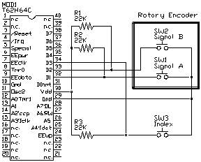
In the next example a quadrature encoding sensor is used with an index sensor to locate the absolute position of a rotating shaft. Although we won't put all the electronics for driving the motor in the schematic, these additional components could easily be incorporated with a motor driving circuit like those talked about earlier.
First, what is a quadrature encoding sensor. An encoding sensor is a collection of switches, either mechanical, optical, or magnetic that indicate the angular position of a shaft. These types of encoders usually have between 16 and 512 positions per revolution. Some encoders produce an absolute binary or Gray's coded position output. The one used in this example is a relative position sensor that produces a quadrature output. The output waveforms look as shown below. When the sensor rotates in one way, signal A's phase leads signal B's, when the sensor rotates the other way, signal B's phase leads signal A's. The sensor electronics need to watch these two signals to increment or decrement a counter. We assume the motor and mechanical inertia of the system prevent the signals from changing too fast. This is a reasonable assumption when the motor's output shaft is geared down. If there are more than 20 phases per second per signal, dedicated electronics are needed to count the position.

Earlier we said the quadrature encoder gives relative position. By this we mean an additional signal, called an "index", is required in the system to reset the position count in the controller. When power is first applied to the system, the controller must turn the motor on in the direction toward the index mark. When the index signal switches, the controller must reset the counter. After this step, the controller has the absolute position of the system mechanics.

