Submitted by:
Glenn Clark
VersaTech Electronics
The programs and drawings shown below are taken from the examples section of the manual.
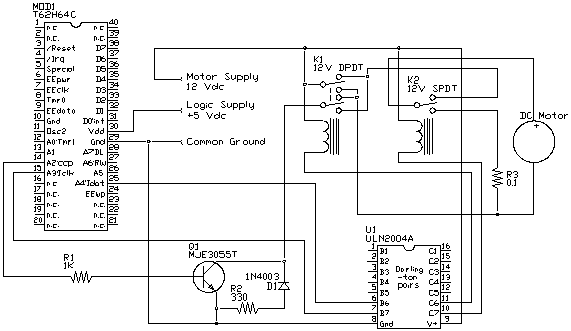
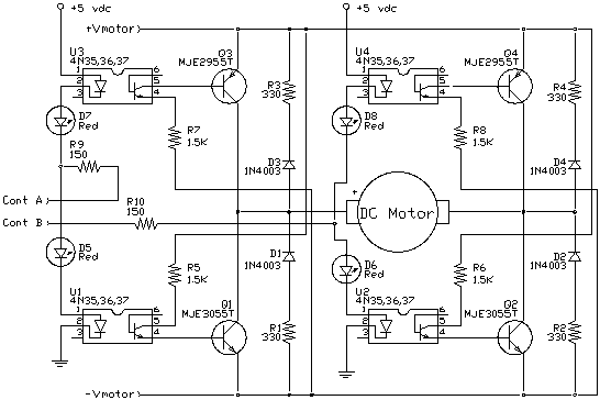
Now that we have a means for varying the drive to a motor or some source like it, we may need to reverse the direction of the motor or provide a means for braking. The easy way to do this is with relays. Driving relays is actually very easy with the TICkit. Our circuit will use an IC which has several transistors in them arranged as Darlington pairs. This single IC will provide buffering for up to 7 relays. We only need to drive two for this example.
Relays are simply magnetically operated switches. When the coil is energized, the switch is thrown. Two different types of relays are used in this example, one is a DPDT (double pole double throw) for motor polarity, and the other is a SPDT (single pole double throw) for braking. The circuit shown below is very similar to the last circuit except that the relays change how the resulting power is applied to the motor. The relay K1 in its un-energized position connects the motor to achieve forward rotation (forward rotation is assigned by convention of the motor's manufacturer . When positive voltage is applied to the motor lead marked as positive the motor rotates forward). When K1 energizes, the positive of the motor is connected to ground and the output of the PWM is connected to the negative of the motor, making it rotate in reverse.
Relay K2 controls whether the positive of the motor connects to K1' output or if it is shorted through R3 to the negative of the motor. When K2 is un-energized, the motor sees power from the PWM and direction control circuits. When K2 is energized, the motor is connected to a resistive load that impedes the rotation of the motor. If the motor is not shorted when power is removed, it simply coasts. If the motor is geared there may be some self braking, but braking capabilities are usually required.

The following program illustrates these types of controls. The program sets up the PWM, turns the motor on at half speed and rotates it forward for 1 second, removes power and brakes the motor for 3 seconds, reverses direction and powers the motor at 1/4 speed for 2 seconds, removes power and lets the motor coast for 6 seconds, then repeats the process. A real control program probably has some type of user interface for setting motor speed and direction instead of a hard coded routine. You can use the console statements with the download cable to make an elementary front end as a further programming exercise. An item that is usually found in this type of program is an acceleration and deceleration routine. If you have delicate instruments or payload handled by the motor, you don't want it damaged by inertial forces as your motor slams on and off. Play with different ideas and see what you come up with. This is the essential electro-mechanical motor control circuit.
As you can see from the program, to energize a relay, perform a pin_high() on the specified I/O pin. In this example we are using a 12 volt supply for both the motor and the relays. If the motor is really large and has large acceleration loads, you might need to separate the supplies to prevent the relays from dropping when the motor starts. Also, you might use a larger voltage on the motors, which either the relay's voltage will need to match, or a separate lower voltage supply will be required for the relays.
