Submitted by:
Glenn Clark
VersaTech Electronics
The programs and drawings shown below are taken from the examples section of the manual.
We have already touched on the idea of pulse width modulation in our blinking LED example. PWM is a way of producing a variable power/voltage/current output from a switched output. The TICkit 62 has no analog output, only digital (switched) outputs, so PWM is the only direct way to produce a variable (analog) output. The TICkit 62 has two methods of producing PWM directly. The first uses a built in function called "cycles()" to produce a square wave of given duration, frequency, and duty cycle, on any of the general purpose I/O pins. The second method uses some dedicated hardware built into the TICkit 62 processor for continuously producing a PWM output. This method can only produce PWM on the pin labeled "A2'CCP". CCP stands for Counter/Capture/PWM. This second method can actually perform 10 bit PWM.
DEF tic62_c
LIB fbasic.lib

GLOBAL word duty_cycle ; make room for a variable and give it a name

DEF wave_length 256   ; produces a pulse frequency of approx 11KHz
DEF per_level 20      ; produces a ramp frequency of approx 550Hz

FUNC none main
BEGIN
    pin_low( pin_d4 )       ; make pin D4 an output
    =( duty_cycle, wave_length )
    REP
        REP
            cycles( pin_d4, per_level, duty_cycle, wave_length )
            --( duty_cycle )
        UNTIL ==( duty_cycle, 0 )

        REP
            ++( duty_cycle )
            cycles( pin_d4, per_level, duty_cycle, wave_length )
        UNTIL ==( duty_cycle, wave_length )
    LOOP
ENDFUN
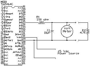
This program uses the cycles function to produce a ramping voltage between 0 and 5 vdc. The meter can be a voltage meter or an O-scope if you have one. If R2 is disconnected, the voltage repeatedly ramps up to 5 volts then ramps down to zero cleanly. With R2 in circuit, there is a relatively large spike at the end of the ramp and the ramp gets sluggish toward 5 volts. These distortions occur because R2 loads the circuit when there are program interruptions in the PWM output.

As this circuit demonstrates, the cycles() method of producing PWM is sufficient only if the circuit will not be loaded very heavily. There is a relationship which exists between the driving capability of the PWM device (the TICkit and series resistor), the size of the capacitor, the frequency of the PWM signal, and the load size. If the frequency is high enough, even larger loads can use this method. Notice in the program that follows, that each time the cycles function executes, only 20 square waves are generated. Between each execution of the cycles function, the program does some math and some flow control. Even though these other program steps take only a small fraction of time, it is enough of a break in the PWM output to create a glitch when there is much load at all on the output. This type of glitch is virtually unavoidable when using a software emulation method to generate PWM.
One way in which to get a larger driving capacity out of this method of PWM is to connect the unloaded PWM output to some type of linear amplifier like an audio output amp. This works well and eliminates the problem with the limited drive capacity of the TICkit as well as the "glitches" when the TICkit is in between cycles() functions as the program executes. The problem with this method is that it is very power in-efficient. When the output of the amplifier is mid-way between ground and max voltage output, the difference between the max voltage and the output must be dissipated by the amplifier. This generates a lot of heat and wastes a lot of power. The following diagrams show the amplifier arrangement and compare it to a variable resistor.
The power dissipated by the resistor is equal to the product of the voltage it drops times the current flowing through it. A switch is like a very large value adjustable resistor adjusted to one extreme or the other. So either it drops zero voltage, or it passes zero current. In either extreme the power dissipated is zero because the product of anything multiplied by zero is zero. Now, if this resistor is adjusted mid-way, like our amplifier producing a half voltage output, the power is equal to 1/2 of the max voltage times the current drawn by the load. Just for argument, assume we are dealing with a 5 volt system and a load that draws 1 amp at 2.5 volts. If the amplifier is outputting 2.5 volts it must be dropping the remaining voltage (2.5 volts). This means that it is dissipating 2.5 watts (2.5 v * 1 amp). Which is exactly what the load is consuming. Half of our supply energy is wasted and we have a significant heat problem.
Now lets deal with the actual best way to use the TICkit 62 to control a DC motor. This approach uses the built in hardware to generate continuous PWM. Instead of a built in software routine turning a general purpose pin on and off, the TICkit 62 uses dedicated hardware to turn pin A2'CCP on and off on the basis of values contained in special registers. The TICkit 62 provides functions to set these registers and the hardware does the rest independent of what our program is doing. This is called background functionality. We control an internal timer, called timer2, to generate the pulse frequency for our PWM. Timer2 has a control, a period, and a count register. These determine the frequency of the PWM. To make the TICkit 62 actually perform PWM, the CCP registers must be configured. These are the control and CCP data registers. Once configured, you write to the CCP data register to control the duty cycle. There are symbolic names for values that can be write to the control register. These constants are defined in the token library. The program looks like this:
DEF tic62_c
LIB fbasic.lib

GLOBAL word ccp_reg  ; CCP register is actually a word (16 bit)
                     ; but only the lower byte (8 bits) are used.
                     ; The high byte is used internally as a
                     ; buffer. The Alias statement lets us
                     ; conveniently refer to the low byte
ALIAS byte ccp_duty ccp_reg 0

FUNC none main
BEGIN
    pin_low( pin_a2 )
    tmr2_cont_set( tmr2_con_on )
    tmr2_period_set( 255b )       ; this produces a pulse frequency
    ccp1_cont_set( ccp_pwm )      ; of 19531 Hz. Clock frequency/256
    =( ccp_duty, 0b )     ; now our CCP unit is set up to do PWM
    REP                   ; this is the main loop
        REP               ; this loop decreases motor speed
            --( ccp_duty )
            ccp1_reg_set( ccp_reg )
            delay( 10 )
        UNTIL ==( ccp_duty, 0b )

        REP               ; this loop increases motor speed
            ccp1_reg_set( ccp_reg )
            delay( 10 )
            ++( ccp_duty )
        UNTIL ==( ccp_duty, 0b )
    LOOP
ENDFUN
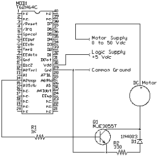
This circuit controls a relatively large DC motor running at a supply voltage of up to 50 volts follows. This circuit can conceivably switch up to 5 amps with this single switching transistor and flyback diode. Realistically, however, you should only use this circuit for switching 2 amps or less. If you are going to switch higher currents, R1 should be reduced to 150 ohms. No interface components are shown in the diagram.

The transistor, Q1 is operated as a saturation switch. This means that when A2 is high, the current allowed to flow through the transistor via R1 is significantly greater than the load current divided by the transistors Gain. Said another way, we are driving the transistor way on. This makes the transistor act like a switch, either it is off and has no current flow, or it is on and has virtually no resistance. The diode D1 and resistor R2 are designed to drain off the parasitic flyback voltage created when current is removed from an inductor (the motor in this case). Bypassing the reverse EMF or flyback voltage safeguards components and reduces heat load on Q1.
Protean Logic Inc. Copyright 05/05/04 Top of Page