AN009 - Using 74HC165 and 74HC594/595 with serial methods
to increase I/O capacity
Submitted by:
This application note gives examples of common shift register logic
ICs that can be used to increase the I/O capacity of a TICkit (or any other
microprocessor). A ZIP file containing the schematics
and code for this note can be downloaded by following the link. For input
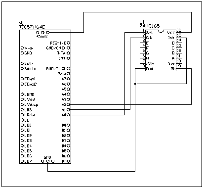
purposes, a 74HC165 8bit shift register is used. With this device 8 inputs
are loaded into the shift register when the S/L pin is brought low. When
the S/L pin is returned high, the level of input H appears on the Qh output
and can be read by the TICkit. Upon each successive clock, another of the
inputs appears on the Qh output. By clocking the device 8 times all the
inputs at the time of the S/L latch can be read into the TICkit. By daisy-chaining
multiple 74HC165 devices together, as many inputs as are desired can be
achieved using only 3 of the TICkit pins. 2 of these 3 pins can be shared
with other serial devices, also. The code of the library file: U74165.lib
shows how to clock the data into the TICkit and follows the diagram.

; Functions to control a 74HC165 shift register for additional inputs
; These functions rely on three defines to work properly
; u74165_rst   =  Chip Select pin     Must have a separate line
; u74165_clk   =  Clock control pin   Can share a data line with other device '
; u74165_data  =  data pin            must be a dedicated line or 'ored with'
                                      a resistance (>10k) to another serial
                                      data line

;*******************************************
; Function to Read a Byte from the u74165
;*******************************************

FUNC byte read_u74165
    LOCAL byte count_out 8b
BEGIN
    pin_low( u74165_clk )       ; make pin an output, needed when sharing buss
    pin_low( u74165_rst )       ; latch enable chip
    pin_high( u74165_rst )      ; latches inputs into shift register

    =( exit_value, 0b )
    REPEAT
        =( exit_value, <<( exit_value ))
        IF pin_in( u74165_data )
            ++( exit_value )
        ENDIF

        pulse_out_high( u74165_clk, 1w )
        --( count_out )
    UNTIL ==( count_out, 0b )
ENDFUN
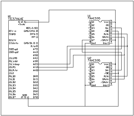
In the same way that a 74165 can be used to gain additional inputs,
the 74594 or 74595 can be used to gain additional outputs. These devices
are shift registers with LATCHED parallel outputs. The latched outputs
are necessary to prevent level glitches as data is shifted into the device.
The 74594 is the preferred device because it has an input pin to clear the
outputs. However, the 74594 is harder to find a source for than the 74595.
Two other ICs the 74597 and 74596 exist which are open collector versions
of the same devices, respectively, and can be used for driving up to 35ma
per output. This is suitable for most smaller 12v relays, and almost all LED's. This circuit below shows an 8bit output circuit while the diagram
that follows shows a 16bit output circuit achieved by daisy-chaining two
devices together.


The library code for writing 16 bits out output to two devices is as
follows:
; Functions to control a 74HC594 latched shift register for additional outputs
; These functions rely on three defines to work properly
; u74594_rst   =  Chip Select pin     Must have a separate line
; u74594_clk   =  Clock control pin   Can share a data line with other device '
; u74594_data  =  data pin            Can share a data line I.E. a LCD'

;*******************************************
; Function to Write a word out to the u74594
;*******************************************

FUNC none write_u74594
    PARAM word comm_data
    LOCAL byte count_out 16b
BEGIN
    pin_low( u74594_clk )       ; make pin an output, needed when sharing buss
    pin_low( u74594_rst )       ; latch enable chip

    REPEAT
        IF <>( and( comm_data, 0y1000000000000000w ), 0b )
            pin_high( u74594_data )
        ELSE
            pin_low( u74594_data )
        ENDIF

        pulse_out_high( u74594_clk, 1w )
        =( comm_data, <<( comm_data ))
        --( count_out )
    UNTIL ==( count_out, 0b )

    pin_high( u74594_rst )       ; disable chip
ENDFUN
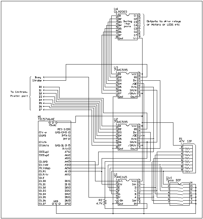
The final example of this application note shows how 74165 devices and
74595 devices can be combined in a typical real application. This circuit
shows the 74165 being used to read DIP switches for setup information and
the 74595s being used for controlling relays and for sending output to
a centronix type printer. These are suitable uses for this approach since
none of these uses would be expected to require fast level changes. Because
this is a serial interface, this technique is not suitable for fast changing
signals.

This program is not a complete strip chart recording program, but could
easily be made into one with the addition of an LTC1298 for taking voltage
measurements or a D1620 for taking temperature measurements. Use this program
as a skeleton if you have use for this type of program.
; Strip Chart Recording Program. This program serves as an example of
; using 74165 and 74595 devices to implement a simple strip chart
; recording device that prints to an Epson compatible printer.

DEF tic57_e
LIB fbasic.lib

DEF u74165_rst pin_a3
DEF u74165_clk pin_a1
DEF u74165_data pin_a2

LIB u74165.lib

DEF u74594_rst pin_a4
DEF u74594_clk pin_a1
DEF u74594_data pin_a2

LIB u74594w.lib


GLOBAL word outputs ; image of serial outputs
ALIAS byte prn_data outputs 0 ; data bits to printer port
ALIAS byte cont_data outputs 1 ; control outputs for relays etc.

DEF strobe_pin 0y000000001b


GLOBAL byte inputs ; image of serial inputs
                   ; dip switch setting might be used to indicate
                   ; frequency of sampling data and/or relay
                   ; control for heating elements or vacuum controls

DEF busy_pin 0y10000000b


FUNC none prn_char       ; function to send data to the printer
    PARAM byte prn_char
BEGIN
    REP
        =( inputs, read_u74165())
    UNTIL ==( and( inputs, busy_pin ), 0b )
        ; loop until printer is not busy

    =( prn_data, prn_char )
    write_u74594( outputs )
        ; raise strobe pin to high (low= active)

    =( cont_data, and( cont_data, not( strobe_pin )))
    write_u74594( outputs )
        ; stobe data to the printer

    =( cont_data, or( cont_data, strobe_pin ))
    write_u74594( outputs )
        ; raise strobe pin to high (low= active)
ENDFUN


FUNC none prn_string       ; function to send a string the printer
    PARAM word pointer

    LOCAL byte data
    LOCAL word temp_pntr
BEGIN
    =( temp_pntr, pointer )
    =( data, ee_read( pointer ))
    WHILE <>( data, 0b )
       prn_char( data )
       ++( temp_pntr )
       =( data, ee_read( temp_pntr ))
    LOOP
ENDFUN


FUNC none main
BEGIN
    ; should initialize relay or other control data here also
    =( cont_data, or( cont_data, strobe_pin ))
    write_u74594( outputs )
        ; ensure that strobe to printer is inactive

    =( inputs, read_u74165())
        ; read whatever setup data is required

    prn_string( "Strip Chart is now recording..." )
    REP
        ; in this loop is where actual readings would be taken
        ; and graphic commands would be sent to the printer to
        ; draw the chart.
        ; this loop might be combined with some sort of relay control
        ; as in the case of some sort of environmental testing.
        IF ==( and( inputs, 0x7fb ), 0b )
            delay( 100 )
        ELSEIF ==( and( inputs, 0x7fb ), 1b )
            delay( 200 )
        ELSEIF ==( and( inputs, 0x7fb ), 2b )
            delay( 500 )
        ELSEIF ==( and( inputs, 0x7fb ), 3b )
            delay( 1000 )
        ELSEIF ==( and( inputs, 0x7fb ), 4b )
            delay( 2000 )
        ELSEIF ==( and( inputs, 0x7fb ), 5b )
            delay( 5000 )
        ELSEIF ==( and( inputs, 0x7fb ), 6b )
            delay( 10000 )
        ELSEIF ==( and( inputs, 0x7fb ), 7b )
            delay( 20000 )
        ENDIF
    LOOP
ENDFUN
Summary:
Many may recognize the similarity between this approach and common 3-wire
interfaces such as those used by Dallas and National for A/D or time keeping
devices. In fact, these techniques are entirely compatible with these devices.
You may use the same data and clock lines for connecting to any number
of additional 3-wire devices. Only one 74165 device may connect to the
data input line however. This is because the 74165 does not tri-state the
data line. Rather a resistor is used to allow all the other devices on
the data line to "over-power" the 74165 level. The 74165 is seen
by the TICkit only when all other devices connected to the data line are
in a non-selected and therefore tri-state level.
Where suitable, this technique reduces the physical size of a circuit,
simplifies PCB layout and increases current drive capacities per area of
devices.
Protean Logic Inc. Copyright 05/05/04
Top of Page


